


Sliding Door Installation Guide: Rough Opening, Flashing, and Code Compliance


Key Takeaways:
- A compliant sliding door installation requires a rough opening 3/4-1 inch larger than the door frame in both dimensions, a sill pan with a minimum 1/2-inch interior upturn leg per ASTM E2112, and low-expansion closed-cell foam (minimum R-5 per inch) – not high-expansion foam, which bows the jambs irreversibly.
- Standard sliding doors weigh 80-200 lbs per panel and can be installed by one experienced person; lift & slide systems weigh 300-880 lbs, require sill level tolerance of 1/16 inch instead of 1/8 inch, and require a certified installer to keep the manufacturer’s 10-year warranty valid.
- Replacing a patio door requires a building permit in most U.S. states, and the replacement unit must meet IECC 2021 Table R402.1.2 U-Factor thresholds for the applicable climate zone – from 0.22 in Zones 7-8 to 0.40 in Zones 1-2.
- NFRC-certified air leakage values are measured in a laboratory test buck and do not reflect installation quality – improper foam application or a missing interior sill seal can double or triple actual infiltration regardless of what the product label says.
Proper sliding door installation requires a rough opening within 3/4-1 inch of the door frame dimensions and a sill plate level to within 1/8 inch. A code-compliant sill pan flashed per ASTM E2112 is mandatory – not optional – in every exterior patio door installation, and the cavity between frame and framing must be sealed with low-expansion closed-cell foam providing a minimum R-5 per inch. For lift & slide systems weighing 300-880 lbs per panel, the weight, precision tolerances, and compression-seal mechanics demand a certified installer to protect the manufacturer’s 10-year warranty. This guide covers every phase: framing verification, flashing sequence, frame anchoring, panel adjustment, sealing, and the permit requirements that apply in most U.S. jurisdictions when replacing an exterior patio door.
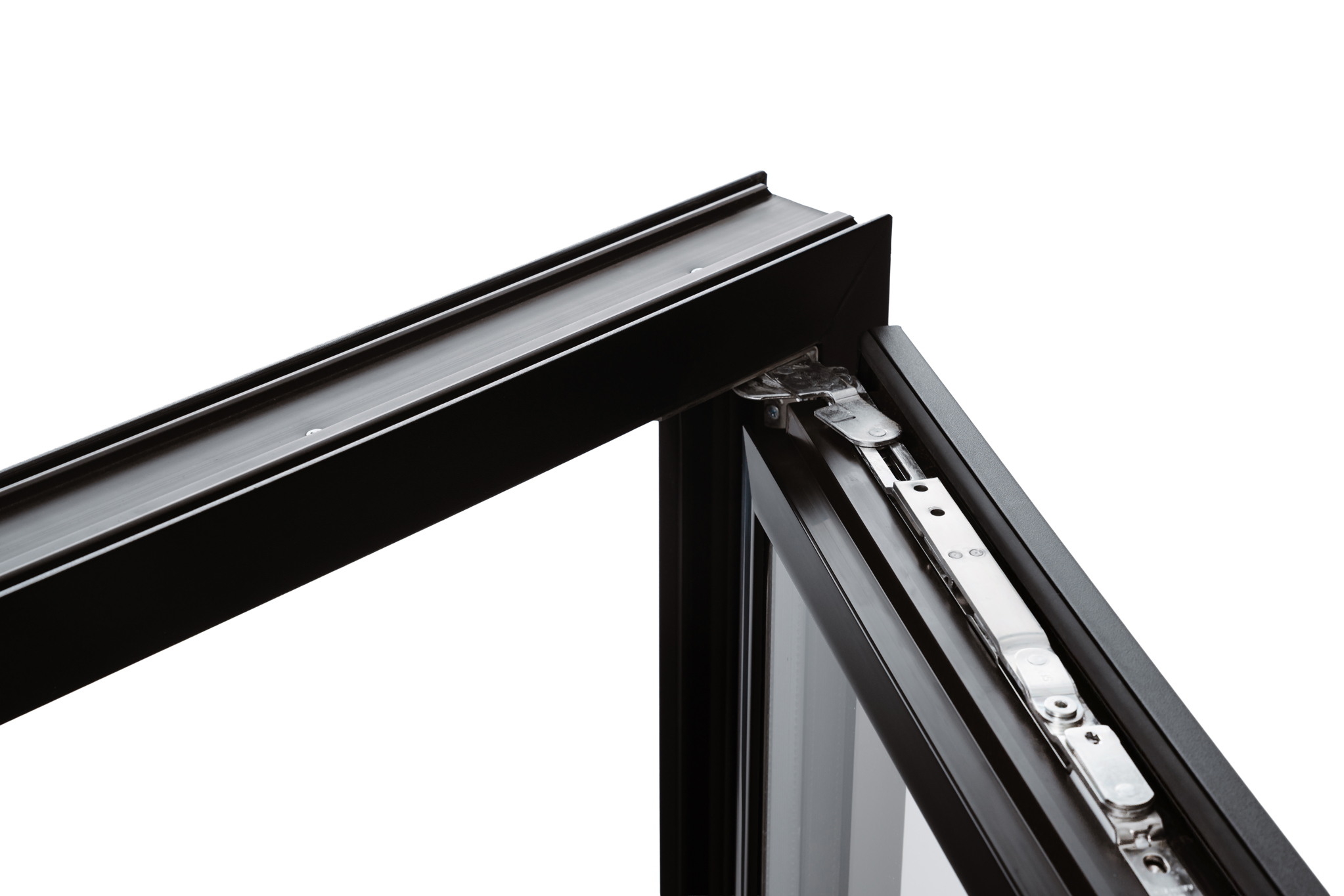
Tools and materials required
- Laser level and 4-foot spirit level
- Tape measure (measure in three locations per dimension)
- Drill/driver with bits, 1½-2” #8 screws (stainless steel in coastal areas)
- Pry bars and utility knife
- Foam gun with low-expansion closed-cell foam (OSI Quad Foam or equivalent ASTM C1320-compliant product)
- Caulk gun with silicone sealant (ultra-low VOC, all-weather rated)
- 6-inch window and door flashing tape (self-adhered membrane)
- High-impact composite shims – not wood, which compresses under load and is susceptible to rot
- J-roller for flashing adhesion
- Sill pan – rigid, flexible, or rubber (mandatory per ASTM E2112 §7)
What rough opening dimensions and structural header does a patio sliding door require?
The rough opening for a patio sliding door must be 3/4-1 inch larger than the door frame in both width and height – consistent with ASTM E2112 field tolerances and manufacturer installation specifications for premium door systems. Some residential installation guides specify only 1/2 inch; that figure is sufficient for lightweight standard doors but leaves insufficient room for composite shimming on heavy uPVC or aluminum units.
Measure the rough opening in three horizontal locations (top, middle, bottom) and three vertical locations (left, center, right). Use the smallest measurement in each axis. A diagonal measurement from upper-left to lower-right and upper-right to lower-left must be within 1/8 inch of each other; if not, the opening is out of square and must be corrected before installation. No amount of shimming corrects a twisted rough opening after the frame is set.
Header sizing is the most frequently under-specified element in residential patio door installations. A standard 6-foot sliding door rough opening requires a minimum 4×10 Douglas Fir header or a double 1.75×9.5 LVL (Laminated Veneer Lumber) beam, per AWC (American Wood Council) Span Tables for Joists and Rafters. For 8-foot and wider openings – common with HORIZON or Aluview Sky+ systems – a double 1.75×11.25 LVL or engineered beam is typically required. The specific sizing must be confirmed by a structural engineer or the local AHJ, as it depends on tributary load above the opening, span, and lumber species. Installations in older wood-frame construction from the 1960s-1990s commonly have undersized headers; always verify before ordering the door unit.
Rough opening checklist:
- Width: 3/4-1 inch greater than door frame width
- Height: 3/4-1 inch greater than door frame height
- Level: sill plate level to within 1/8 inch across the full width
- Plumb: side jambs plumb to within 1/8 inch over full height
- Square: diagonal measurements within 1/8 inch of each other
- Header: correctly sized for span and load per AWC Span Tables – verify with structural engineer or AHJ
- Blocking: solid blocking at sill and both sides of the opening before frame insertion
See the products
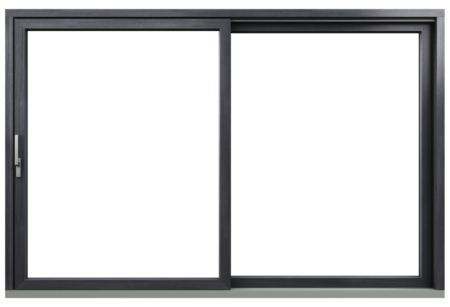

What sill pan geometry does ASTM E2112 require for a sliding patio door?
A sill pan is mandatory in every exterior sliding door installation per ASTM E2112, Section 7 – the standard specifies a minimum 1/2-inch interior upturn leg, a minimum 2-inch exterior downturn leg, and 6-inch upturn legs at both jamb ends. The interior upturn leg (dam) prevents water from migrating inward; the exterior downturn leg directs water onto the weather-resistant barrier (WRB) or away from the structure; the jamb legs seal the lateral edges where water most often enters. Sill pans that terminate flush with the rough opening sides allow water to travel laterally into the framing – the most common source of water damage in sliding door installations, often invisible for 3-5 years but structurally significant by the time it surfaces.
Three sill pan types are acceptable under ASTM E2112: rigid pre-formed pans (aluminum or PVC), flexible membrane pans (self-adhered rubberized asphalt or butyl), and site-formed rubber pan flashing. Rigid pans offer the most dimensional consistency; flexible membranes conform better to irregular sill surfaces. For lift & slide units above 400 lbs, a rigid pan is preferred because membrane-type pans can compress under repeated load and gradually lose the upturn geometry that keeps water out.
Sealant application sequence on the sill pan matters. Apply a continuous bead along the exterior edge, stopping approximately 2 inches from each end. Those gaps are intentional drainage paths – they allow water that bypasses the door sill to exit to the exterior rather than being trapped. Sealing the full perimeter is one of the most common installation errors and converts a moisture-diverting sill into a moisture trap.
Sill pan geometry summary (per ASTM E2112 §7):
- Interior upturn leg: minimum 1/2 inch
- Exterior downturn leg: minimum 2 inches
- Jamb end upturn legs: 6 inches each side
- Drainage void: 2 inches from each jamb end – do not seal these
- Slope: pan must pitch toward exterior – minimum 1/8 inch per foot

How to set and anchor the sliding door frame: shimming sequence, fastener pattern, and plumb verification
Frame anchoring requires three sealant beads on the exterior sheathing before the frame is inserted, stainless steel fasteners in coastal and high-wind zones, and a perfectly straight lock-side jamb. Get any one of these wrong and the door will not seal or lock reliably.
Before the frame enters the rough opening, apply three continuous sealant beads to the exterior sheathing: one on each side and one across the top, aligned with the nailing flange holes so screws pass through the sealant as they are driven. This creates a gasket between the flange and the sheathing. On the weather-resistant barrier (WRB), cut back 1-1/2 inches at both side jambs to allow direct-contact adhesion between the flashing tape and the sheathing. At the head, create a 45-degree flap by cutting the WRB diagonally at the top corners; tape this flap up out of the way until the door is set and head flashing is applied.
Set the frame by tilting it outward at the top, placing the sill into the sill pan first, then rotating the top inward until the nailing flange contacts the sealant beads on the sheathing. Two people are required for frames wider than 6 feet; for lift & slide frames, three people or mechanical assistance. Drive a single 2-inch screw into one top corner, then verify plumb and level before continuing. Once confirmed, fasten through every other nailing flange hole – every hole in coastal areas, using stainless steel.
The lock-side jamb demands extra care. Wide frames (8 feet and wider) tend to bow inward at the center because the nailing flange does not provide continuous bearing. Shim the lock-side jamb at the strike location and drive two 3-inch screws through the jamb into the rough framing. A bowed lock-side jamb creates misalignment between the lock bolt and strike plate, causes air infiltration across the latch side, and prevents consistent multi-point lock engagement on high-performance systems. Verify straightness with a straight-edge or taut string line along the full jamb height before foaming.
Frame anchoring sequence:
- Apply three continuous sealant beads to sheathing at sides and head, aligned with nailing flange holes
- Cut WRB back 1-1/2 inches at jambs; create 45-degree head flap, tape up out of way
- Place sill into sill pan; rotate top inward to contact sheathing sealant beads
- Drive one screw at top corner; verify plumb and level on all axes before continuing
- Fasten every other flange hole (every hole in coastal/high-wind areas with stainless steel)
- Shim lock-side jamb; drive 2×3-inch screws at strike location
- Verify lock-side jamb straightness with straight-edge – zero bow tolerance
Standard sliding door vs. lift & slide: what changes structurally?
Standard sliding doors and lift & slide systems require fundamentally different installation approaches: panel weight ranges from 80-200 lbs (standard) to 300-880 lbs (lift & slide), sill level tolerance tightens from 1/8 inch to 1/16 inch, and installation by a certified installer is required for lift & slide systems to maintain the manufacturer warranty. The air infiltration difference is also significant – a correctly installed lift & slide unit achieves below 0.08 CFM/ft² at 25 Pa (ASTM E283), compared to 0.15-0.30 CFM/ft² for standard sliding doors.
Standard sliding doors – including the OKNOPLAST COMPACT uPVC system – operate on a fixed bottom track: the panel rolls on bottom rollers that maintain continuous contact with the track surface. A single experienced installer can handle standard-width units up to 72 inches.
Lift & slide systems work on a different principle entirely. The OKNOPLAST HORIZON uPVC and the Aluview Sky+, Premium, and Standard aluminum systems all use a multi-point hardware mechanism actuated by the handle: turning it lifts the panel off a perimeter compression seal and onto rollers for sliding, then lowers it back onto the seal when closed. That compression-seal contact is what produces the substantially lower air infiltration compared to standard track systems.
The weight demands different structural preparation. HORIZON panels can reach 780 lbs per panel for large-format triple-glazed configurations (per OKNOPLAST HORIZON product data sheet); Aluview Sky+ panels for oversized openings can approach 880 lbs (per Aluview Sky+ technical specifications). These loads require a reinforced sill threshold with continuous structural support – the threshold cannot span a subfloor gap without solid blocking below. The rough opening sill must be level to within 1/16 inch across the full width, because the lift mechanism engages compression seals at multiple points simultaneously; a non-level sill produces uneven compression and chronic air infiltration on the low side regardless of hardware adjustment.
Key differences: standard sliding vs. lift & slide
- Panel weight: standard 80-200 lbs vs. lift & slide 300-880 lbs
- Bottom track: fixed contact (standard) vs. compression seal with lift mechanism (lift & slide)
- Sill level tolerance: 1/8 inch (standard) vs. 1/16 inch (lift & slide)
- Air infiltration when properly installed: 0.15-0.30 CFM/ft² (standard) vs. below 0.08 CFM/ft² (lift & slide) – per ASTM E283
- Subfloor blocking: recommended (standard) vs. mandatory continuous support (lift & slide)
- Installer: one person feasible for standard; minimum two for lift & slide; installation by a certified installer required for warranty coverage
OKNOPLAST USA requires installation by an authorized partner or certified installer for all HORIZON and Aluview lift & slide systems as a condition of the 10-year product guarantee. Attempting self-installation on a lift & slide unit that subsequently develops air leakage, panel drag, or lock misalignment will typically result in a denied warranty claim, because those failure modes are indistinguishable from improper installation.

How to hang sliding door panels and adjust rollers for smooth operation
Sliding door panels must be hung with rollers retracted to minimum height, then adjusted to a uniform 3/16-inch gap between the bottom rail and the track – uneven roller height creates asymmetric weatherstripping compression and localized air infiltration regardless of the door’s NFRC-certified air leakage rating. If one side of the panel sits lower than the other, that side’s perimeter gasket over-compresses while the opposite side under-compresses, and no NFRC label value compensates for the resulting air infiltration at that point.
For standard sliding systems, retract the rollers to their lowest position by turning adjustment screws counterclockwise before hanging the panel – this reduces the panel’s effective height and allows insertion into the upper track without forcing. Tilt the top of the panel into the upper track first, confirm the rollers are seated, then lower the bottom edge onto the bottom track. Turn the adjustment screw clockwise to raise the panel, counterclockwise to lower. Adjust incrementally and test slide operation after each quarter-turn. The gap between the bottom rail and the track should be uniform at maximum 3/16 inch across the full panel width.
After panel adjustment, install anti-lift blocks or security bars in the upper track. These prevent the panel from being lifted off the track from the exterior, a common forced-entry method on sliding doors without secondary security hardware. High-performance systems like COMPACT and HORIZON incorporate multi-point anti-lift hardware as part of the lock mechanism, but it must be correctly engaged at installation.
Installing lock and handle hardware
Strike plate alignment must be verified within 1/8 inch of the lock bolt trajectory in all axes – thermal expansion between the installation temperature and peak summer or winter conditions can produce misalignment that prevents full lock engagement seasonally, even if the hardware operates correctly at the time of installation. Set the strike plate position before final fastening. On multi-point systems, engage all lock points simultaneously before tightening any single fastener, ensuring uniform compression around the full perimeter.
How to seal a sliding patio door frame: foam specification, CFM/ft² targets, and perimeter weatherstripping
The cavity between the door frame and the rough opening framing must be sealed with low-expansion closed-cell foam only (ASTM C1320-compliant, minimum R-5 per inch) – high-expansion foam deflects jambs inward, binding the panel and preventing multi-point lock engagement; once it sets, the damage is irreversible without removing the frame. Apply a single bead with the foam gun tip slightly back from the nailing flange; allow the first pass to partially set (approximately 5 minutes) before filling the full cavity. Fill the lock-side jamb gap completely to create solid backing that reduces panel bounce on closing.
Before foaming, apply a continuous sealant bead between the sill pan and the door sill along the entire bottom edge. Use an application tool to press the sealant fully into the gap – a surface bead bridges the gap visually without actually sealing it. This interior sill seal is separate from the exterior sill pan drainage geometry. Both must be present: the sill pan manages bulk water; the interior seal stops air infiltration and condensation from tracking along the bottom frame.
NFRC-certified air leakage values – for example, below 0.08 CFM/ft² at 25 Pa for a properly installed lift & slide unit, tested per ASTM E283 – are measured in a rigid laboratory test buck. In field conditions, improper foam application can double or triple the actual infiltration rate regardless of what the product label says. The certification describes the product’s potential; the installation determines whether that potential is ever reached. There is no field adjustment that recovers performance lost to a bowed jamb or a missed interior sill seal.
Complete sealing sequence:
- Apply interior sill sealant bead between sill pan and door sill; press fully into gap with application tool
- Foam side jamb cavities with low-expansion closed-cell foam (R-5/inch minimum, ASTM C1320); fill lock-side jamb fully
- Apply flashing tape to both side jambs over the nailing flange, extending minimum 1 inch past the top flange hole
- Apply flashing tape along the head, overlapping the side flashing by minimum 1 inch
- Apply sealant (two 3/8-inch nominal beads) along top of frame against the nailing flange
- Drive a 2-inch screw through a drip cap onto the top of the frame; drop the WRB head flap down over the drip cap
- Flash over the drip cap and WRB flap with flashing tape; use J-roller to eliminate all air pockets
- Apply exterior trim sealant with paintable silicone caulk; do not seal weep holes or sill pan drainage voids

When does patio door installation require a building permit and IECC compliance?
Replacing a patio door requires a building permit in most U.S. states – including California, Massachusetts, New York, Washington, and Florida – and when a permit is required, the replacement unit must meet IECC 2021 Table R402.1.2 U-Factor thresholds ranging from 0.22 in Climate Zones 7-8 to 0.40 in Zones 1-2. Verify the specific requirement with the local AHJ (Authority Having Jurisdiction) before starting work, as permit triggers and the applicable energy code version vary by jurisdiction.
The most common triggers requiring a permit for patio door replacement are: structural alteration to the rough opening or header, installation in a new wall location, or a jurisdiction that has adopted the IRC 2021 energy compliance requirement for fenestration replacements. Florida requires a permit for all exterior door replacements regardless of scope. When a permit is required, the replacement door must comply with IECC 2021 Table R402.1.2 fenestration U-Factor and SHGC requirements for the applicable climate zone:
- Climate Zone 1 (South Florida, Hawaii): U-Factor ≤ 0.40, SHGC ≤ 0.25
- Climate Zone 2 (Texas Gulf Coast, Central Florida): U-Factor ≤ 0.40, SHGC ≤ 0.25
- Climate Zone 3 (Atlanta, Los Angeles, Phoenix): U-Factor ≤ 0.30, SHGC ≤ 0.25
- Climate Zone 4 (DC, Nashville, Seattle): U-Factor ≤ 0.30, SHGC ≤ 0.40
- Climate Zone 5 (Chicago, Denver, Boston): U-Factor ≤ 0.27, SHGC any
- Climate Zone 6 (Minneapolis, Billings, Burlington VT): U-Factor ≤ 0.27, SHGC any
- Climate Zone 7-8 (Fairbanks, Anchorage): U-Factor ≤ 0.22, SHGC any
ENERGY STAR certification offers a straightforward compliance path in most jurisdictions, since its thresholds align with or exceed IECC requirements. The OKNOPLAST COMPACT uPVC sliding system and HORIZON lift & slide system are NFRC-certified with U-Factor ratings that meet ENERGY STAR thresholds for their applicable zones. Confirm the U-Factor of the selected configuration before submitting permit documentation, as it varies with glazing package and frame size.
The §25C Energy Efficient Home Improvement Credit (IRS) provides up to $600 per exterior door unit, with a $1,200 annual household cap, for NFRC-certified products meeting ENERGY STAR Most Efficient criteria. The credit applies to product cost only – not installation labor – and is claimed in the tax year the installation is completed. Confirm the selected configuration carries both the NFRC certification and the ENERGY STAR Most Efficient designation before purchase; standard ENERGY STAR certification does not satisfy the Most Efficient requirement.
How does installation quality affect your NFRC air leakage rating and manufacturer warranty?
NFRC air leakage ratings – expressed as CFM/ft² at 25 Pa differential pressure, tested per ASTM E283 – are measured on the door unit itself in a rigid laboratory test buck. They do not include the interface between the door frame and the rough opening framing. That interface – the sill-to-sill-pan seal, the jamb cavity foam, the head flashing sequence – is entirely determined by installation quality and is not captured in the NFRC label value.
Passive House builders and high-performance envelope contractors consistently report that field-installed units achieve 30-60% higher actual air infiltration than their NFRC-labeled values when installation does not follow manufacturer specifications, per DOE Building America program field studies and PHIUS-certified project documentation. The most common failure points: incomplete interior sill seal (air and water track under the threshold), high-expansion foam bowing a jamb (breaks the perimeter gasket compression), and head flashing not integrated with the WRB (water infiltrates through the wall assembly, not through the door unit). These failures do not show up as visible water intrusion initially – they appear first as elevated heating and cooling costs and condensation at the door perimeter in cold weather.
OKNOPLAST’s 10-year product guarantee covers manufacturing defects. It does not cover performance failures from installation errors, including: warped jambs caused by high-expansion foam, degraded weatherstripping from uneven roller height, water infiltration through the wall assembly rather than through the door unit, and hardware failure from misaligned strike plates. Most premium fenestration manufacturers carry equivalent exclusions. This is precisely why OKNOPLAST USA requires installation by an authorized partner for all HORIZON and Aluview lift & slide systems: the liability for performance is shared between the product and the installation, and only one of those can be factory-controlled.
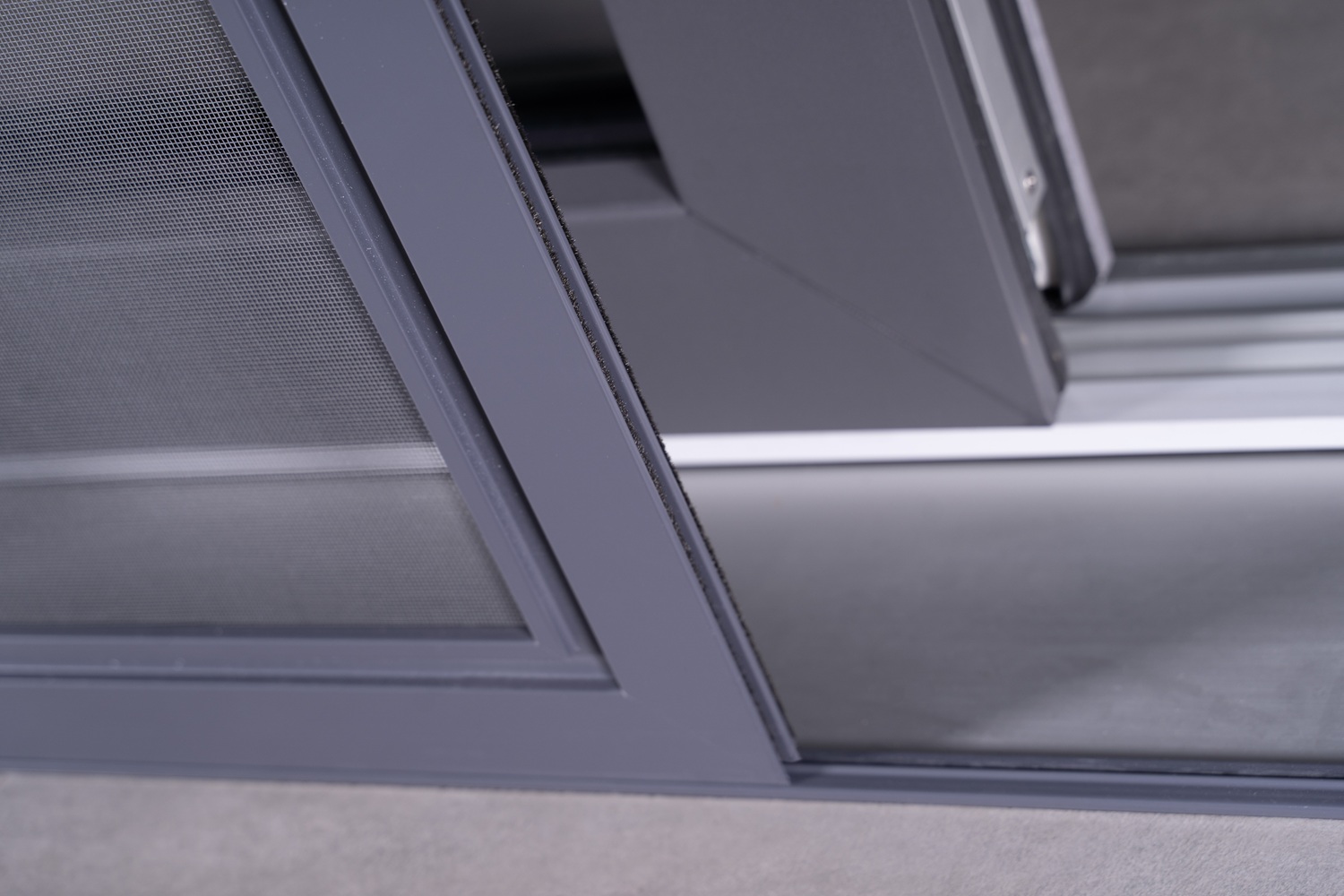
How to maintain a patio sliding door: track cleaning, lubrication frequency, and roller adjustment?
Sliding patio door tracks require cleaning and lubrication at minimum twice per year – spring and fall – using silicone-based lubricant only. Petroleum-based products including WD-40 and oil-based silicone degrade EPDM and TPE weatherstripping compounds, leave a residue that attracts debris, and accelerate seal failure that becomes detectable as increased air infiltration within 2-3 years of regular use.
Track cleaning procedure: vacuum to remove loose debris, then wipe the track with a damp cloth. Do not use petroleum-based cleaners. After cleaning, apply a thin film of dry silicone spray to the track surface and bottom roller contact areas. On lift & slide systems, also apply silicone lubricant to the lifting ramp surfaces on the threshold. Clean after any significant windstorm or nearby construction, as grit embedded in the track acts as an abrasive on roller bearings and accelerates wear.
Roller adjustment is the most common maintenance task. Over 2-3 years of operation, roller height adjustment screws gradually migrate due to repeated use and thermal cycling. If the door requires more than light finger pressure to slide, or drags at one point in its travel, re-adjust before assuming the rollers need replacement. Return to a uniform 3/16-inch gap between the bottom rail and the track. If re-adjustment does not resolve the issue, inspect the rollers for flat spots or embedded debris – both indicate the rollers need replacing.
Weatherstripping inspection: close the door and check for visible daylight around the perimeter from the interior side in a darkened room. Any visible light indicates weatherstripping compression loss or panel misalignment. On lift & slide systems, confirm the panel lowers fully onto the compression seal when the handle is returned to the closed position – partial lift mechanism engagement is the most common cause of air infiltration complaints in these systems and is typically resolved by hardware adjustment, not weatherstripping replacement.
FAQ
The rough opening must be 3/4-1 inch larger than the door frame in both width and height. Measure in three locations per axis and use the smallest measurement. The sill must be level to within 1/8 inch, jambs plumb to within 1/8 inch, and diagonal measurements within 1/8 inch of each other. For lift & slide systems, the sill level tolerance tightens to 1/16 inch. Verify that the structural header is correctly sized for the span before ordering – undersized headers are the most common structural deficiency found in patio door openings.
In most U.S. jurisdictions, yes. California, Massachusetts, New York, Washington, and Florida all require permits for exterior door replacements in most circumstances; Florida requires one for every exterior door replacement without exception. When a permit is required, the new door must meet IECC 2021 Table R402.1.2 U-Factor thresholds for the applicable climate zone. Always verify with the local AHJ before starting work.
Standard sliding doors roll on a fixed bottom track and weigh 80-200 lbs per panel; one experienced installer can handle standard-width units. Lift & slide systems raise the panel off a compression seal onto rollers when opening, achieving air infiltration below 0.08 CFM/ft² at 25 Pa (ASTM E283) versus 0.15-0.30 CFM/ft² for standard sliding. Lift & slide panels weigh 300-880 lbs, require sill level tolerance of 1/16 inch versus 1/8 inch, need minimum two-person installation, and require a certified installer to maintain the manufacturer’s 10-year warranty.
Low-expansion closed-cell foam only – ASTM C1320-compliant products such as OSI Quad Foam or equivalent. High-expansion foam deflects jambs inward, binding the panel and preventing full lock engagement; once it sets, correcting the damage requires removing the frame. Closed-cell foam provides minimum R-5 per inch and does not absorb moisture. Apply in a single bead pass, allow to partially set for 5 minutes, then fill the remaining cavity. Fill the lock-side jamb gap fully to reduce panel bounce. Never use high-expansion foam around any window or door frame.
Yes, if the replacement door is NFRC-certified and meets ENERGY STAR Most Efficient criteria. The §25C Energy Efficient Home Improvement Credit provides up to $600 per exterior door unit, with a $1,200 annual household cap (IRS, tax year 2025). The credit applies to product cost only, not installation labor, and is claimed in the tax year of installation. Standard ENERGY STAR certification is not sufficient – the unit must carry the Most Efficient designation specifically.
A sill pan is required by ASTM E2112 and by most building codes that reference it because the door sill is the most vulnerable water intrusion point in any exterior door assembly. The sill pan collects and redirects water that bypasses the door threshold during wind-driven rain to the exterior via two intentional drainage voids at the jamb ends. Without a sill pan, that water contacts the rough sill framing; rot typically becomes visible after 3-5 years but is often already structurally significant well before that.
A correctly installed sliding door slides the full travel with one-finger pressure, shows no daylight at the perimeter in a darkened room with the door closed, and shows no smoke deflection from a lit incense stick held at the frame perimeter on a windy day – any of these three checks failing indicates an installation defect, not a product defect. A fourth check: inspect the exterior sill after rain. Water pooling on the interior sill indicates a missing sill pan or sealed drainage voids.
The required DP (Design Pressure) rating is determined by the calculated wind pressure for the specific location and exposure category per ASCE 7-22. For Exposure B (suburban terrain), velocity pressure coefficients (Kz) are 0.57 at 15 feet, 0.76 at 30 feet, and 0.85 at 40 feet. The OKNOPLAST COMPACT and PAVA systems carry DP-80 ratings. For Miami-Dade and Broward counties – designated HVHZ (High-Velocity Hurricane Zone) under the Florida Building Code – products require a Notice of Acceptance (NOA) based on ASTM E1886/E1996 impact testing; verify requirements with the local building department before specifying.
Clean and lubricate tracks twice per year: spring and fall. Use dry silicone spray only – not WD-40, not petroleum-based oil, not oil-based silicone. Petroleum products degrade EPDM and TPE weatherstripping compounds and leave a grit-trapping residue that accelerates track wear. After vacuuming and wiping the track clean, apply a thin film of dry silicone spray to the track surface and roller contact areas. On lift & slide systems, also apply to the threshold lifting ramp surfaces.
IECC 2021 Table R402.1.2 requires a maximum U-Factor of 0.27 for fenestration in Climate Zone 5 (Chicago, Denver, Boston, and equivalent locations), which aligns with ENERGY STAR’s Northern zone threshold of U-Factor ≤ 0.27, SHGC ≤ 0.40. For PHIUS passive building compliance, the OKNOPLAST PAVA system achieves U-Factor as low as 0.14 – placing it within PHIUS compliance territory for most Zone 5 configurations – and the OKNOPLAST HORIZON lift & slide system delivers equivalent U-Factor performance with the same triple-glazing package.


Let’s talk about your project!
Request a quote, discuss specifications, or get help choosing the right system
Send a request
"*" indicates required fields